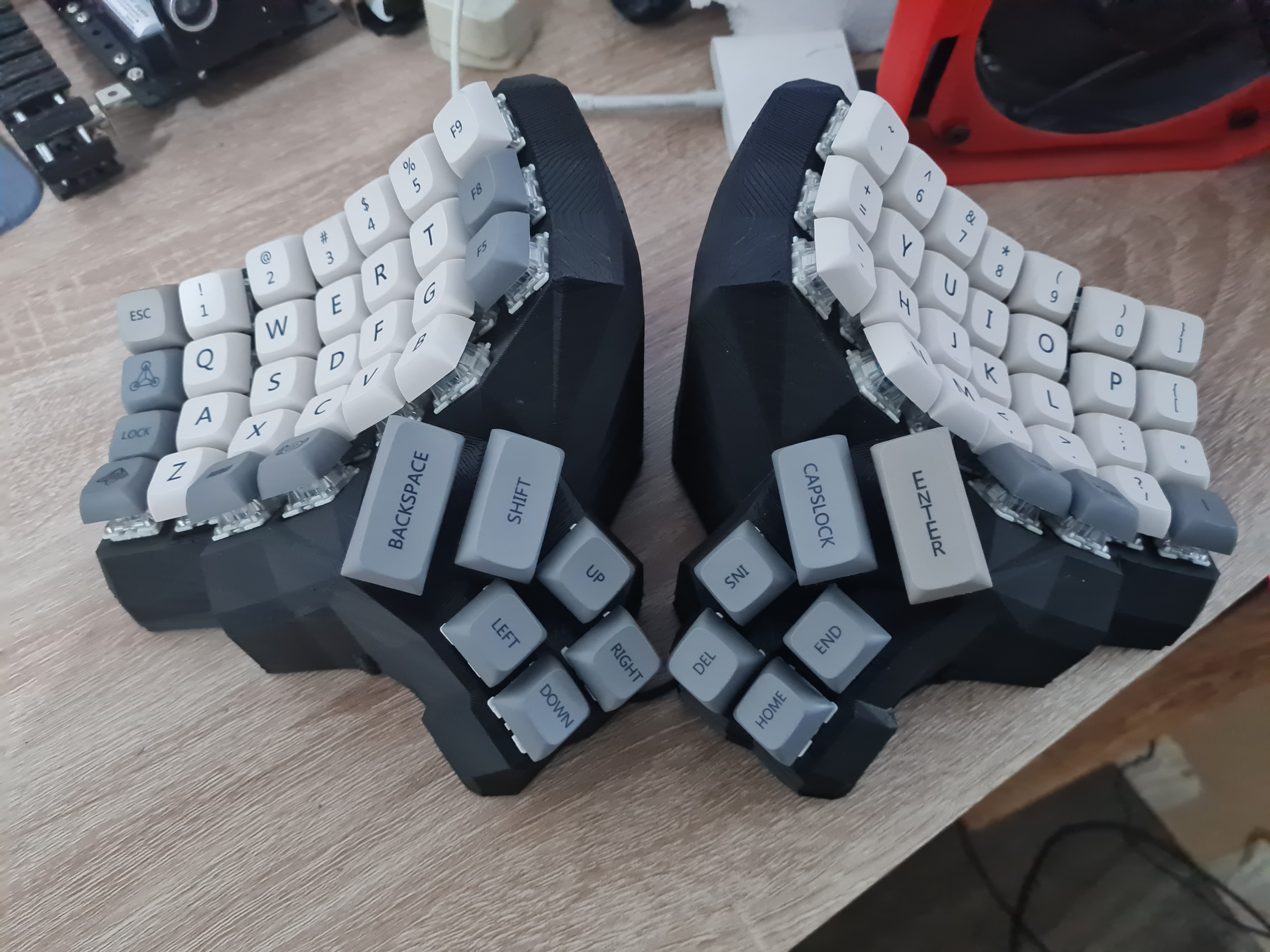
The third Keyboard I've made
I like this keyboard
Last post I mentioned that I have a keyboard in mind that I really wanted, but due to my limited understanding oh how to use my 3d printer I wasn’t be able to print it immediately and had to settle for something less, well the redox is still cool and does the job of being a split keyboard but the ergonomic design of the dactyl manuform just takes the cake.
Le Keyboard:
 Dactyl Manuform
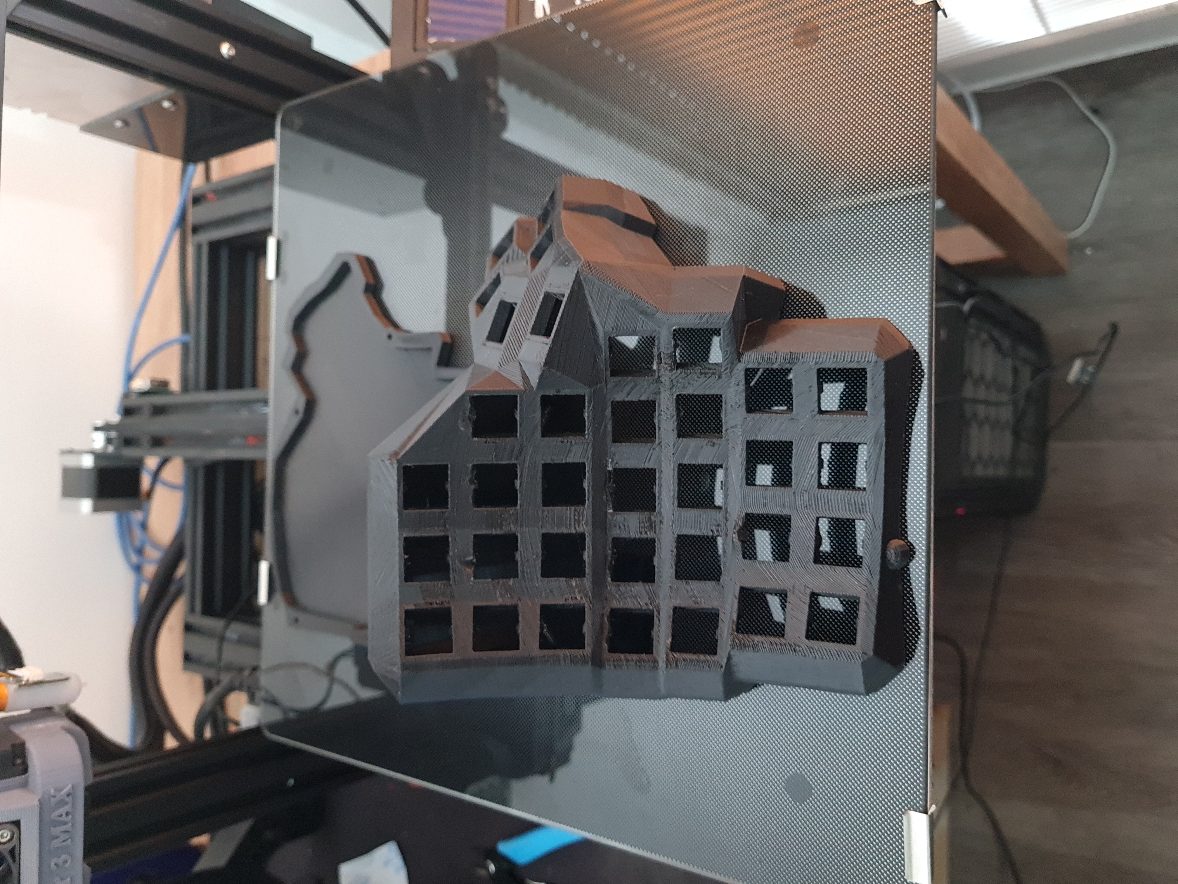
This year after experementing with different configurations with my ender 3 I was able to print various models and it made me more comfortable in checking out more advanced designs, I’ve even managed to print me a replacement fan mount for it since the stock one got melted away, and in the process off installing the printed one I’ve kind of broke the heating element from my printer and managed to replace it, so yeah more experience in the maintenance of my printer, through the various models I’ve printed I took a shot in printing the original keyboard I was hoping to create on my first try, the Dactyl Manuform, a simple google search would show how cool this ergonomic keyboard looks like, what I was missing last time was the configurations for supports un printing.
Printing Le Keyb:
 Le Keyboard
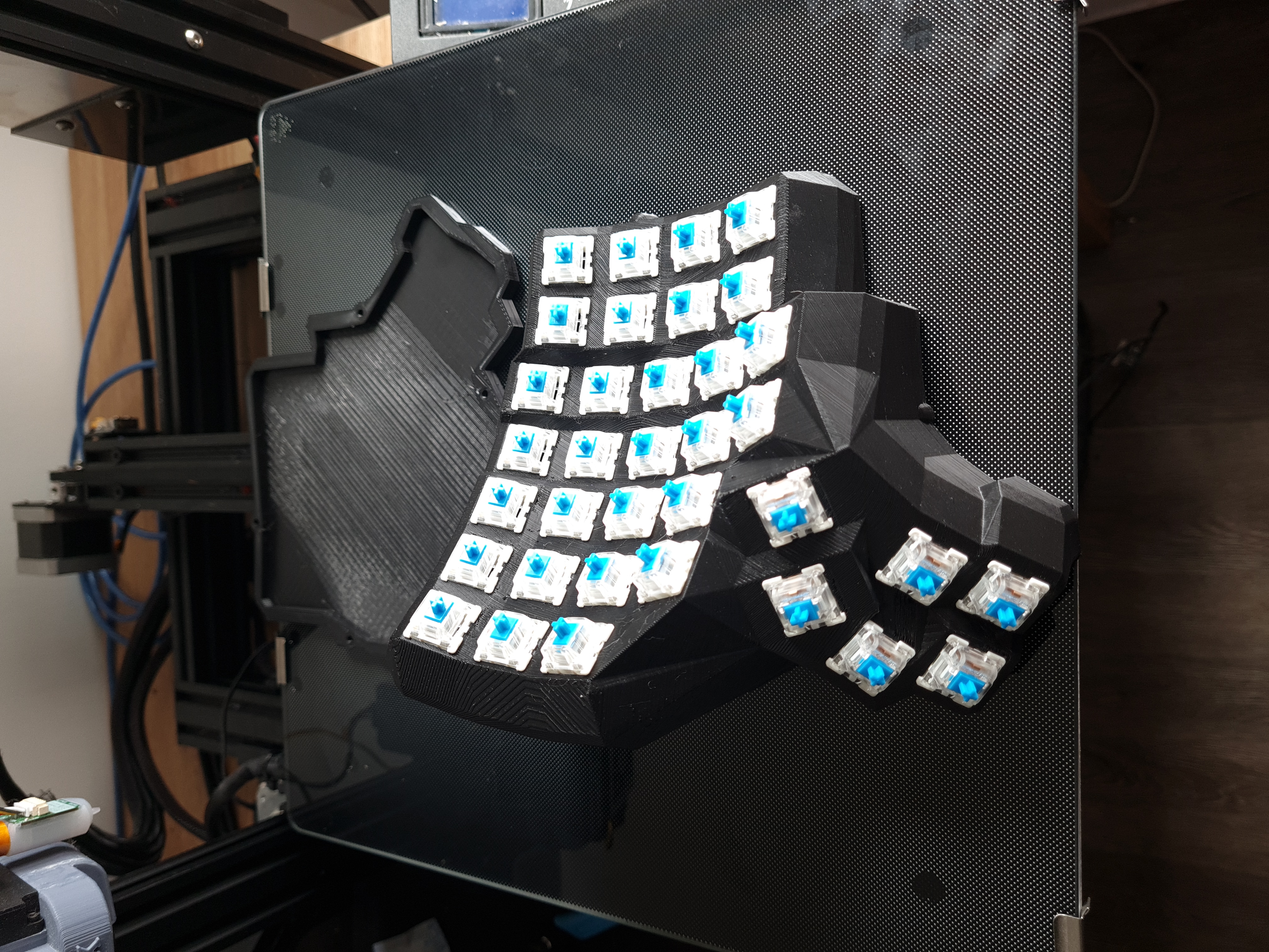
Ofcourse blue switches:
 Blue Switches
How I made it
The printing part was only time consuming, needing to print for about 54hrs per frame was a drag, there were some time that I had to restart printing since the power got cutoff midway, another was that the fillament got completely depleted mid print since the keyboard frames are too big and consumes a lot of fillament, but all in all the parts were printed in just over a week last February.
The next big part of the creation process of the keyboard was hand soldering the diodes and the microcontroller in place, at first I skeptical as I noticed that soldering on a bent surface wouldn’t be as easy as the when I soldered my redox keyboard in place, so I had to be smart and make sure that the wires wouldn’t cross or get tangled with each other, this process actually got into me for more than it should, good thing that I consulted my fiance, and she just suggested that I should probably isolate the switches that seems to be too far away from the others, so that gave me a eureka moment of maybe extending the current layouts in qmk configurator and make blanks for the unused switch coordinates.
Circuit Diagram or what is it called, I’m new to electronics:
Circuit Diagram
The circuit diagram should be straight forward I’m no electronics major nor took any course or classes in it so apologies to the circuit correctors of the internet, it should be noted though that the wires going outward vertically are considered the column wires and the dangling wires horizontally are the row wires as to be configured in the qmk firmware code and should be wired to the correct pin in the pro-micro, if everything is clear with the circuit/wiring diagram what I’ve did actually looked like this.
 Soldered wires
Rinse and repeat in the other frame and actually we’re good to go.
Layout and QMK
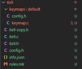
The qmk firmware package actually supports most known keyboard layouts available there, but since I didn’t officially followed the wiring diagram and the layout set for this Dactyl Manuform, I had to edit my own just for the sake of flashing the pro-micro for this keyboard, what I’ve ended up is below.
Custom Layout:

Code for the custom layout can be found Here:
I’ve copied the actual layout from the 5x7 layout since it resembles the layout of the keyboard that I’ve printed the most, but I renamed it to 6x9 since that is the actual number or rows and comlumns present in my wiring diagram, after adding the new layout I had to edit one more file in the qmk configurator.
The file is qmk_firmware\keyboards\handwired\dactyl_manuform\dactyl_manuform.h, I just had to add the new layout in the header file so that qmk could see it.
#elif defined(KEYBOARD_handwired_dactyl_manuform_5x7)
#    include "5x7.h"
#elif defined(KEYBOARD_handwired_dactyl_manuform_6x9)
#    include "6x9.h"
#elif defined(KEYBOARD_handwired_dactyl_manuform_6x6)
#    include "6x6.h"
There are other configuration files that needs to be changed based on the soldering decisions made, like which pins were used for rows and which ones are used for columns, the pin to be used for serial.c so that the two pro-micros can communicate to each other, and the actual key layout for the switches.
First one is the pin to be used for the serial.c to connect the two frames, qmk_firmware\keyboards\handwired\dactyl_manuform\config.h, out of the box of the qmk configurator this is set to D0, I instead used D1 so that my wires has no gap in it.
/* serial.c configuration for split keyboard */
#define SOFT_SERIAL_PIN D1
Next is for the row and column pins in qmk_firmware\keyboards\handwired\dactyl_manuform\6x9\config.h, I have used the configuration below and soldered the dangling wires from my circuit to the respective pins, make sure that pins are soldered or wired correctly to the rows and columns, I’ve spent a whole night trying to figure out this issue and it was due to mis alignment of soldering to pins.
// wiring of each half
#define MATRIX_ROW_PINS { D0, D4, C6, D7, E6, B4}
#define MATRIX_COL_PINS { F4, F5, F6, F7, B1, B3, B2, B6, B5 }
Lastly is the actual layout of the keys in qmk_firmware\keyboards\handwired\dactyl_manuform\6x9\keymaps\default\keymap.c, this is basically what ever layout you want, and just make sure that you are using the correct keycaps positions for the actual keyboard. We are using keycodes here so if you don’t know the actual keycodes a simple google search should be made.
const uint16_t PROGMEM keymaps[][MATRIX_ROWS][MATRIX_COLS] = {
    [_QWERTY] = LAYOUT_6x9(
        // left hand
                KC_ESC,    KC_1,    KC_2,    KC_3,   KC_4,   KC_5,   KC_F9,
                KC_TAB,    KC_Q,    KC_W,    KC_E,   KC_R,   KC_T,   KC_F8,
                KC_CAPS,   KC_A,    KC_S,    KC_D,   KC_F,   KC_G,   KC_F5,
                KC_LCTL,   KC_Z,    KC_X,    KC_C,   KC_V,   KC_B,
                   KC_LWIN,   KC_LOPT,
                                            KC_SPC, OSM(MOD_LSFT),
                                                        KC_RGHT, KC_UP,
                                                        KC_DOWN, KC_LEFT,
        // right hand
            KC_GRV,  KC_6,    KC_7,    KC_8,     KC_9,     KC_0,     KC_RBRC,
            KC_EQL,  KC_Y,    KC_U,    KC_I,     KC_O,     KC_P,     KC_LBRC,
            KC_MINS, KC_H,    KC_J,    KC_K,     KC_L,     KC_SCLN,  KC_QUOT,
                     KC_N,    KC_M,    KC_COMM,  KC_DOT,   KC_SLSH,  KC_BSLS,
                                                KC_PGUP, KC_PGDN,
                    TT(_FN), KC_ENT,
        KC_DEL, KC_BSPC,
        KC_HOME, KC_END
    ),
Another configuration that is supposed to configured is the qmk_firmware\keyboards\handwired\dactyl_manuform\6x9\keymaps\default\config.h, just comment out which side are you flashing, this is basically the side where you want to attach your USB to.
#define MASTER_LEFT
// #define MASTER_RIGHT
In flashing the keyboard I just use the qmk msys tool the command line one, you can use what ever you want avrdude or whatever, the command for flashing with the custom layout is below:
qmk flash -kb handwired/dactyl_manuform/6x9 -km default
PS don’t forget to short the RST to GROUND when flashing as you need to enter programming mode in the pro-micro.
Comments
Post a comment on GitHub